(+61) 1300 654 616
ZWmech Piping Pro
Orthogonal 2D/3D, Isometric and P&ID Piping made easy...
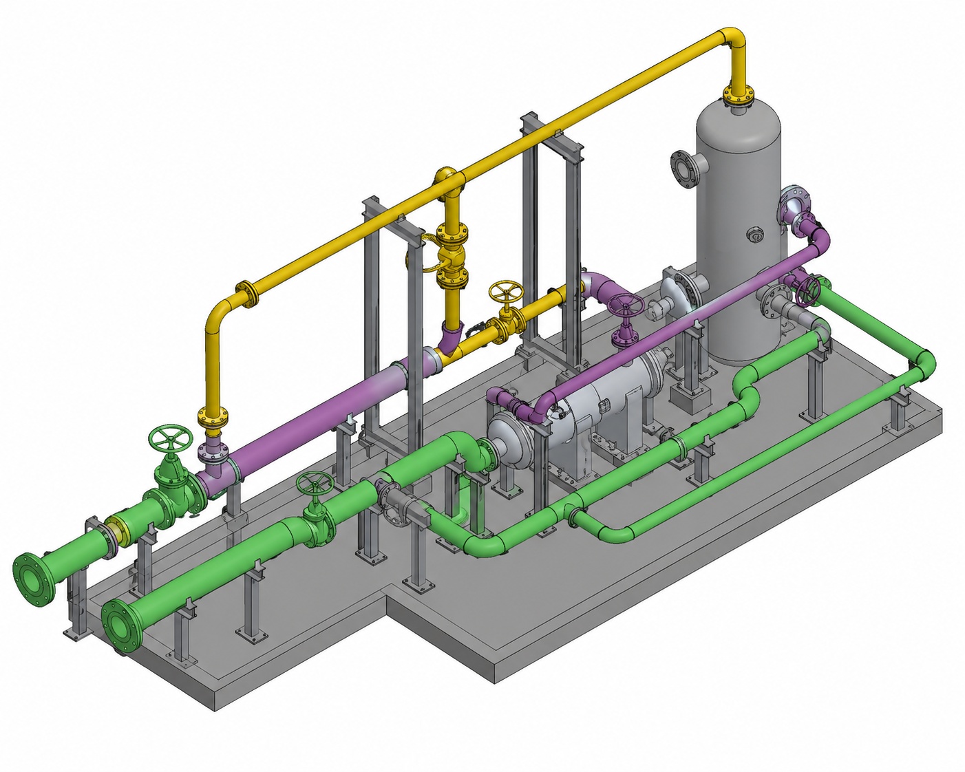
The ZWmech Piping software module Includes a comprehensive range of pipe, pipe fittings, flanges and valves. These include welded, flanged,threaded, screwed, ductile iron & cast iron, "Victaulic" stainless, PVC... piping systems. The module is equipped with features like: Auto-BOM. Customised database, easy to use... The module also draws in Single line, double line, 3D and Isometric.
The module also includes: fabricated piping, hangers, clamps, vessels, pumps... and much more!
ZWmech works with all version of ZWCAD
|
Comprehensive Piping drawing module for drawing simple and complex piping systems for all engineering industries, including:
|
Modules include:
Main Features:
- 2D (Single line & Double) & 3D
- Comprehensive range of pipe & fittings
- Auto-BOM - fully customisable
- BOM Descriptions can be easily edited
- Database editor included
- Several draw options
- Insulation, customisable layers
- Easy to use.
Types of Pipe & fittings included:
- Butt Welded
- Socket Welded
- Screwed
- Grooved
- Cast Iron (Flanged)
- Ductile Iron (Flanged)
- Ductile Iron (Grooved)
- DI - Mechanical Joint
- Stainless Steel Tube
- Soil Piping (No-Hub)
- PVC
- PVC-DWV
- Copper
- PE
and more...
Sizes:
- Pipe size range from DN 15 - 900
(1/2"-36" NB + 1/16 - 3/4" Tube) -DIN, ISO & ANSI - Welded Fittings: DN 15 - 900 (1/2"-36" NB)
- SW & Screwed Fittings: DN 6 - 100 (1/4"-4" NB)
- Victaulic: DN 15 - 600 (1/2"-24" NB)
- Cast Iron (Flg): DN 25 - 450 (1"-18" NB)
- Ductile Iron (Flg)/Grooved/MJ: DN 80 - 1600 (3"-64" NB)
- Stainless Steel (OD)Tube: DN 6 - 100 (1/4"-4" NB)
- Sanitary Piping DN 15 - 150 (1/2"-6" NB)
- Tubing: DN 8-16 (1/4-16" NB)
- PVC-U, PVC-Sch80 & PVC-DWV: DN 15-300 (1/2"-12")
- Copper DN 15 - 100 (1/2"-4" NB)
- PE-BW DN 15 - 1000 (1/2"-40" NB)
Flanges:
- Blind
- Plate
- Bossed
- Welding neck
- Slip-on
- Lap Joint
- Ring Joint (RTJ)
- Long Neck
- Socket weld
- Table A - Table J (Australian)
- DIN PN6-PN100
- BS PN6-PN100
- ANSI: 150-2500
- and User Defined flanges
Valves:
- Ball valves
- Gate valves
- Glove valves
- Check valves
- Angle valves
- Plug valves
- 3-Way
- 4-Way
- Butterfly valves
- Control valves
- and User Defined valves (several design options)
Isometric Piping
The Pipe Isometric Utility will generate pipe isometric diagrams and pipe spools drawings.
Main Features:
- Comprehensive range of pipe & fittings
- Auto-BOM - fully customisable
- BOM Descriptions can be easily edited
- Database editor included
- Sizes of symbols can be changed by user
- Several scaling options
- Custom symbols can be added
- Iso-Dimensioning tools included
- Insulation, customisable layers...
- Easy to use
Iso Piping BOM customization options include:
- BOM Fields can be turned On/Off
- Custom BOM descriptions of pipe/fittings
- BOM Balloons options
- Several leader styles
- BOM Stock Codes option
- Custom BOM remarks
- Custom BOM ratings notes
- Custom BOM field length, width and insertion
- Custom layers, text font, text size...
- Custom fields headers...
Other Modules
Pipe Schematic/Single Line Pipe Diagram
This is a Single line pipe generator. The routine will allow the user to effortlessly draw simple or complex pipe schematics. The user is simply asked to pick points to generate the pipe and at each point the user can pick from a comprehensive icon menu to select the appropriate fitting, valve, pump gauge or hanger. The user is also given the option to draw a LEGEND of the used symbols and/or to form a Bill Of Materials of the fittings and pipes used to draw the schematic or single line pipe diagram.
Vessels
Main Features:
- Easy change of design parameters
- 2D and 3D option
- Horizontal & verstival vessels
- Several nozzelscan be added to vessel body & heads
(Nozzel size, flange type and location - fully customisable)
Heads type include:
- Ellipsoidal
- Hemisherical
- ASME Flanged & Dished
- Flat
Drawing mode:
- Complete,
- Heads or vessel body
- Front View
- End View
- Plan view
- Elevations
- 3D.
Centrifugal Pumps
Main Features:
- Easy to change and add new designs
- Design parameters fully customizable
- Save pump designs for later use
- Front, end & plan view draw elevations
- Add the designed pump to your drawing with ease.
Pipe Hangers & Clamps
- Pipe clips and Riser clamps
- Saddle Clamps and Guides
- U-Bolt Clamps and Guides
- Pipe Shoes
Main Features:
- Large selection of sizes & designs
- Option to add fasteners
- Display of design safe loads
- Front, end & plan view draw elevations
P&ID Module
The ZWmech P&ID module allows you to build and maintain a library of mechanical symbols to be used in Pipe and Instrumentation Diagram (P&ID) drawings. This application covers the standard Piping and Instrumentation symbology outlined in the ANSI/ISA-S5.1-1986 code.
Main Features
- Easy Customization
The program gives you full control of the symbols sizes, layers used, text size and font, as well as many other settings. The program also lets you add your own symbols with ease.
- Layers Customization
ZWmech P&ID lets you specify the layers settings of each of the main P&ID item groups:
Pipe
Fittings
Equipment
Valves
Instrument Equipment
Instrument Balloons
Symbols
Logic Functions
For each of the above you can set the layer Name, Color and Linetype.
When you start P&ID module, at the top of the program dialogue you will find the layer setting of the selected item. This layer setting will correspond to the Layers configuration setting and will be the layer that Mech-Q will use to draw the item on. However, you can override the layer setting of the current item by entering selecting another layer name, linetype (Pipe only) or color.
- Sizes (or Scales) Configuration
The ZWmech P&ID size settings affect the size appearance of all the different categories of P&ID items. You can change these sizes to suit your requirements
- User Defined Symbols
 One of the important features of the Mech-Q P&ID program is the ability to add new or user defined symbols. User defined symbols can be added to each P&ID item category.
- Auto-BOM
The Module includes the auto-generation of Bill